Gendral Civil Engineering
Routine Vertical Pile Load Test Step by Step

Routine Vertical Pile Load Test Step by Step
- The pile was cast-in-situ in a bore taken to a depth of ———– m from ground level. Boring was accomplished by direct mud circulation method using bentonite slurry to stabilize the borehole. The concrete was placed in the borehole after insertion of the prefabricated reinforced cage, using a 200 mm dia tremie pipe. The installation of pile was in accordance with the Indian Standard code IS: 2911 (Part I / Sec 2)-1985 & latest.
- The shape of the pile is circular with a shaft diameter of ——mm.
- Concreting of borehole was done on ——– with M25 opc 53 grade ———-cement was used in making the concrete mix.
- The main longitudinal consist of 13 nos of 20mm bars(Fe 500) and with 8mm lateral bars as helical at 200 mm c/c and spacers stiffeners of 16mm at 2500 mm c/c.
- The design safe load on the pile is 300 tonnes.
- The salient details of the pile no —– are given

Pile Test
- The pile head was chipped off carefully till sound concrete was met with.The projecting reinforcement was cut off and the top finished smooth and any uneven surface was made good with concrete.A 16 mm thick bearing plate was placed on the prepared head to receive the jack base plaster of paris was used under the plate to ensure its even bedding.

- The load was applied by means of a hydraulic jack reacting against a loaded platform.The jack reacted against rolled steel joist,which was held down by a loaded platform.Load test details are given.
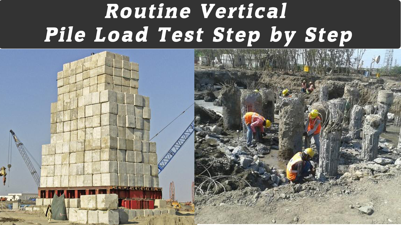
- The kentledge consists of concrete blocks stacked over the platform and had an overall weight at about 669 tonnes. Care was taken in the placement ot kentledge to ensure that the center of gravity of the kentledge was, as tar as practicable, co-axial with the axis of the pile.
- Settlements were recorded using tour dial gauges with least count of 0.01 mm. The gauges were positioned at nearly equal distance around the pile,fixed on immovable datum bars, as described in Indian Standard IS: 2911 (Part 4) 1985 & latest.
- The load was applied in increments of about 20 percent of the design load. The pressure was read from a pressure gauge with a least count of 20 kg/cm2 attached to the hydraulic pump. The jack has ram area of 1428.04 cm2.
- Maintained load method was adopted. as per IS: 2911 (Part 4). The load increments were continued till the final load of 600 tonnes was achieved.
- Time – settlement observations were made at regular intervals during the period when the applied load was kept constant.
- The loading was commenced at time —– on date———- and continued till it reached a value 600 tonnes at 18hrs on the same day ——–.At this level,the loading was maintained for 24 hours upto 18 hours on the second day—–,unloading was then carried out in stages by releasing the jacking pressure,and rebound observations were also made.


